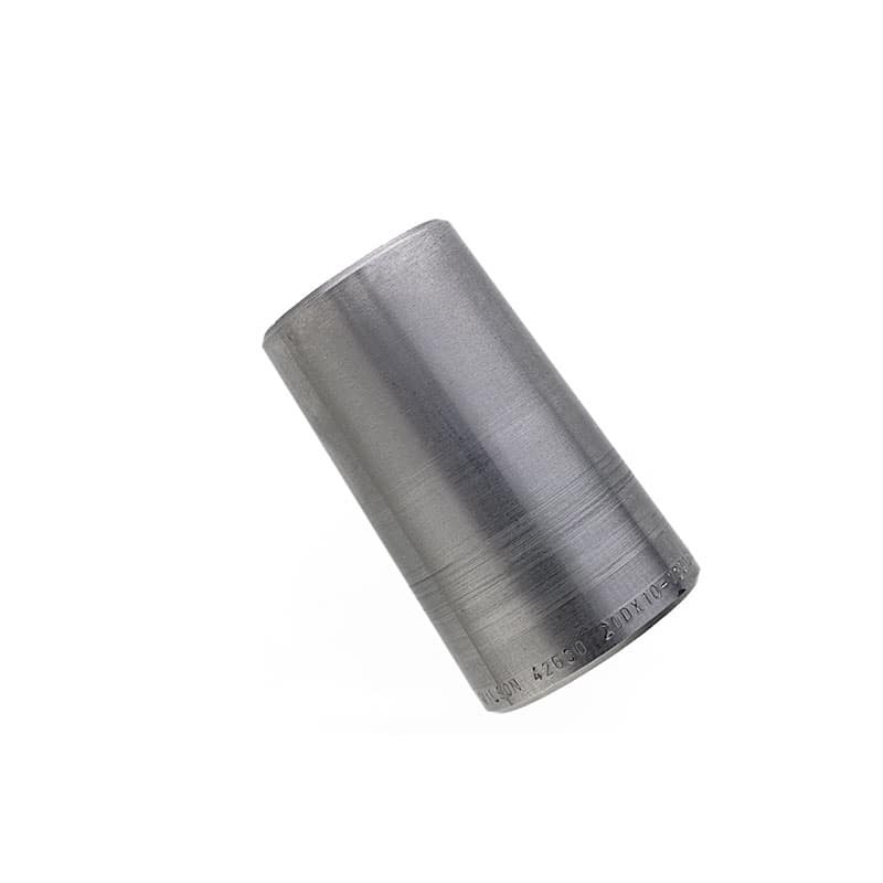
Shell Assembly:
- The shell is constructed either from pipe or rolled plate metal. For economic reasons, steel is the most commonly used material, and when applications involving extreme temperatures and corrosion resistance, others metals or alloys are specified. Using off-the-shelf pope reduces manufacturing costs and lead time to deliver to the end customer. A consistent inner shell diameter or ‘roundness’ is need to minimize the baffle spacing on the outside edge, excessive space reduces performance as the fluid tends to channel and bypasses the core. Roundness is increased typically by using a mandrel and expanding the shell around it, or by double rolling the shell after welding the longitudinal seam. In some cases, although extreme, the shell is cast and then bored out until the correct inner diameter is achieved.
- When fluid velocity at the nozzle is high, an ‘impingement’ plate is specified to distribute fluid evenly in the tubes, thereby preventing fluid-induced erosion, vibration and cavitation. Impingement plates effectively eliminate the need to configure a full tube bundle, which would otherwise provide less available surface. An impingement plate can also be installed above the shell thereby allowing a full tube count and therefore maximizing shell space.
Tubes:
- Heat exchangers with shell diameters of 10 inches to more than 100 are typically manufactured to industry standards. Commonly, 0.625 to 1.5" tubing used in exchangers is made from low carbon steel, Admiralty, copper, copper-nickel, stainless steel, Hastelloy, Inconel, or titanium.
- Tubes can be drawn and thus seamless, or welded. High quality electro resistance welded tubes display good grain structure at the weld joints. Extruded tubes with fins and interior rifling are sometimes specified for certain heat transfer applications. Often, surface enhancements are added to increase the available surface or aid in fluid turbulence, thereby increasing the operative heat transfer rate. Finned tubes are recommended when the shell-side fluid have a considerably lower heat transfer coefficient than the tube-side fluid. Note, the diameter of the finned tube is slightly smaller than the un-finned areas thus allowing the tubes to be installed easily through the baffles and tube supports during assembly while minimizing fluid bypass.
- A U-tube design finds itself in applications when the thermal difference between the fluid flows would otherwise result in excessive thermal expansion of the tubes. Typical U-tube bundles contain less tube surface area as traditional straight tube bundles due to the bended end radius, on the curved ends and thus cannot be cleaned easily. Furthermore, the interior tubes on a U-tube design are difficult to replace and often requiring the removal of additional tubes on the outer layer; typical solutions to this are to simply plug the failed tubes.
Bonnets and End Channels:
- Bonnets / end channels regulate the flow of fluid in the tube-side circuit, they are typically fabricated or cast. They are mounted against the tube sheet with a bolt and gasket assembly; many designs include a ‘machine grooved’ channel in the tube sheet sealing the joint.
- If one or more passes are intended, the head may include pass ribs that direct flow through the tube bundle. Pass ribs are aligned on either end to provide effective fluid velocities through an equal number of tubes at a time ensuring a constant, even fluid velocity and pressure drop throughout the bundle.
- Shell and tube configurations with up to (4) passes are the most common, however specialty designs do allow 20 or more crossings. The tube sheet configuration in a multi-pass shell and tube design must have provisions for the pass ribs, requiring either removal of tubes to allow a low cost straight pass rib or alternately a pass rib with curves around the tubes adding cost to the manufacture process. When a full bundle count is needed for the thermal requirement, machine pass ribs usually prevent the need to ‘upsize’ to the next larger shell diameter.
- The material used in the cast bonnets / heads used in smaller diameters (ie 15” or less) are typically, poured from iron, steel, bronze, Hastelloy, nickel plated, or stainless steel. Pipe connections are normally NPT, others including SAE, tri-clamp, ASME flanged, BSPP, and others types are available.
Baffles:
- Baffles function in two ways, during assembly they function as tube guides, in operation they prevent vibration from flow induced eddies, last but most importantly they direct shell-side fluids across the bundle increasing velocity and turbulence effectively increasing the rate of heat transfer.
- All baffles must have diameter slightly smaller than the shell in order to fit, however tolerances must be tight enough to avoid a performance loss as a result of fluid bypass around the baffles. This is where the concept of ‘shell roundness’ is of up most importance in sealing off the otherwise would be bypass around the baffle.
- Baffles are usually stamped / punched, or machined drilled; such configurations vary based on size and application. Material selection must be compatible with the shell side fluid to avoid failure as a result of corrosion. It is not uncommon for some punched baffle designs to include a lip around the tube hole to provide more surfaces against the tube to reduce wear on the adjoining parts. Tube holes must be precisely manufactured to allow easy assembly and possible field tube replacement, all the while minimizing fluid flow through the hole and against the tube wall.
- In typical liquid applications, baffles occupy between 20-30% of the shell diameter; whereas in a gas application with a necessary lower pressure drop, baffles with 40-45% of shell diameter are used . Baffle placement requires an overlap at one or more tubes in a row to provide adequate tube support. Additionally baffles are spaced evenly throughout the shell to aid in reducing pressure drop and even fluid velocity.


